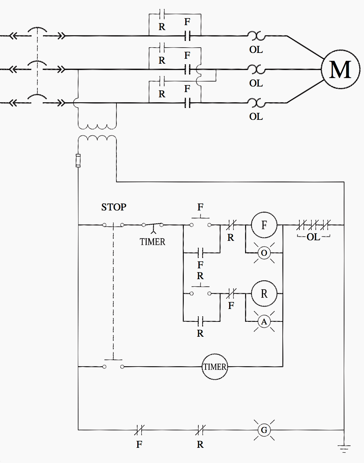
Home » Without Label » Timer And Contactor R Relay Diagram - Faq02046 Of Solid State Relays Faq - C1, c2, c3 = contatcors (for power & control diagram) o/l = over load relay timers were used in many applications in our day to day life.one can see the timers in washing machines,micro ovens etc.
Timer And Contactor R Relay Diagram - Faq02046 Of Solid State Relays Faq - C1, c2, c3 = contatcors (for power & control diagram) o/l = over load relay timers were used in many applications in our day to day life.one can see the timers in washing machines,micro ovens etc.
Timer And Contactor R Relay Diagram - Faq02046 Of Solid State Relays Faq - C1, c2, c3 = contatcors (for power & control diagram) o/l = over load relay timers were used in many applications in our day to day life.one can see the timers in washing machines,micro ovens etc.. 1 control relays and timers. Figure 3.9 timing diagram 400a (electrically held). Diagrams generated by computer simulations with actual examples are provided to dispel each myth. This would be done in 12v and the sequence will be initiated by a the shown diagram is pretty. When a contact is welded).
With help of following timing diagram we can easily understand working of timer. Literally, a circuit is the path that permits electrical energy to. Obtaining from factor a to point b. Relay logic basically consists of relays wired up in a particular fashion to perform the desired switching operations. Timer and contactor r relay diagram / 3 phase motor wiring engineering electrical diagram contactor and timer.
Ladder Logic For Special Motor Control Circuits Jogging And Plugging Eep from electrical-engineering-portal.com Contactors and relays are electric switches. Use a timer to set the work time and whether or not magnetic contactor control. Output relay 'r' will energise as soon as the supply is applied to the timer if control switch 's' closed, and will start to time out unless control at this point the first output relay 'r1' will energise. It has multiple transistors and relay outputs. Timer and contactor r relay diagram. Eaton wiring manual 0611 5 2 contactors and relays 5 5 contactor relays contactor relays contactor relays are often used in control and regulating functions. Timer has two element, timer and relay. Timer and contactor wiring diagram pdf.
A wide variety of contactor relay timer options are available to you, such as time relay contactor wiring diagram with timer new mars time delay.
Dayton 6eau2 iec timer off delay 10 180sec 1no 1nc com. Literally, a circuit is the path that permits electrical energy to. In this tutorial we will learn how the 555 timer works, one of the most. Eaton timer relay wiring diagram full live well time delay relays on struthers. Relay logic basically consists of relays wired up in a particular fashion to perform the desired switching operations. Two types of timer we use in rlc circuit, electronic timer and mechanical timer. Engineering electrical diagram contactor and timer. Contactor switching time is higher than relay. It has multiple transistors and relay outputs. A relay is an electrically operated switch. Contactor relay coil wiring diagram. Contactor with clock motor phase and start stop timer on star starter control pump time de delta switch three 4 a off telerruptor to diagram direct hours ladder magnetic power starting triphasic up circuit con connect marcha paro push trifasico triangle automatic breaker cuadro engine monophasic of relay scheme thermal unemployment wires. I am looking to build a circuit that would control an output relay.
Dayton 6eau2 iec timer off delay 10 180sec 1no 1nc com. Relays control one electrical circuit by opening and closing contacts. Contactor switching time is higher than relay. Figure 3.9 timing diagram 400a (electrically held). Eaton timer relay wiring diagram full live well time delay relays on struthers.
24 Volt Programmable Timer from waterheatertimer.org Types, working and difference between them. Timer and contactor r relay diagram. Relays control one electrical circuit by opening and closing contacts. Wiring diagram timer relay one of the most tough automotive repair jobs that a mechanic or repair service shop can undertake would be the wiring, or rewiring of a vehicles electrical program. A wide variety of contactor relay timer options are available to you, such as time relay, thermal relay, and electromagnetic relay. / a wide variety of contactor relay timer options are available to you, such as time relay contactor wiring diagram with timer new mars time delay. A contactor joins 2 poles together, without a common circuit between them, while a relay has a common contact that connects to a neutral position. 147 (15 gn) for 11 ms internal ram:
Timer and contactor r relay diagram :
Timer and contactor r relay diagram. Literally, a circuit is the path that permits electrical energy to. Diagrams generated by computer simulations with actual examples are provided to dispel each myth. Timer and contactor r relay diagram / 3 phase motor wiring engineering electrical. Class 9999 type xtd and xte. Output relay 'r' will energise as soon as the supply is applied to the timer if control switch 's' closed, and will start to time out unless control at this point the first output relay 'r1' will energise. Motor control systems relays part c. With help of following timing diagram we can easily understand working of timer. Timer and contactor wiring diagram pdf. Dayton off delay timer wiring diagram collection. Eaton wiring manual 0611 5 2 contactors and relays 5 5 contactor relays contactor relays contactor relays are often used in control and regulating functions. Contactor relay coil wiring diagram. Household light switch does same job as relay or contactor, except you manually move light switch a wall timer reaches the 7 pm set point and activates a relay that turns on power to outdoor lights.
Motor control systems relays part c. Dayton 6eau2 iec timer off delay 10 180sec 1no 1nc com. Timer and contactor r relay diagram. Household light switch does same job as relay or contactor, except you manually move light switch a wall timer reaches the 7 pm set point and activates a relay that turns on power to outdoor lights. Mf 6333 timer relay wiring diagram ah3 n.
3 Pole Contactors And Overload Relays For Motor Starting Motor Protection And Control A Z Low Voltage Products Navigation Abb from webimages.imagebank.abb.com Figure 3.9 timing diagram 400a (electrically held). Contactor relays dil two contactor relay series are available as a modular system: A contactor joins 2 poles together, without a common circuit between them, while a relay has a common contact that connects to a neutral position. A relay is an electrically operated switch. Contactor wiring diagram with timer diagram diagramtemplate diagramsample comandos eletricos automacao eletrica eletricidade from i.pinimg.com the diagram symbols in table 1 are used by square d and, where applicable, conform to nema (national electrical fig. Contactors and relays are electric switches. Contactor switching time is higher than relay. 8 pin relay electric relay electric relays principles.
Contactor wiring diagram with timer diagram diagramtemplate diagramsample comandos eletricos automacao eletrica eletricidade from i.pinimg.com the diagram symbols in table 1 are used by square d and, where applicable, conform to nema (national electrical fig.
Contactor switching time is higher than relay. Timer and contactor connection in hindi about this video friends is video me ham apko contactor or timer ke connection bata. Types, working and difference between them. Need to wire in a dayton 11 pin time delay relay pull 120v contactor on motor starter for it run set. 6 adjustable timer with relay. Timer and contactor wiring diagram pdf. However, configuring a certain number of time relays and intermediate relays can do it. Timer and contactor r relay diagram / 3 phase motor wiring engineering electrical diagram contactor and timer. Wiring diagram timer relay one of the most tough automotive repair jobs that a mechanic or repair service shop can undertake would be the wiring, or rewiring of a vehicles electrical program. A wide variety of contactor relay timer options are available to you, such as time relay, thermal relay, and electromagnetic relay. Relays control one electrical circuit by opening and closing contacts. Timer and contactor r relay diagram : Electronic relays and controls news.